
From 3D model to finished drawing, in one click.
Draftneer details your parts the way a designer would: it picks the views, sheet and scale, dimensions holes, bends, diameters and sections, and fills in title block, parts list and balloons. You keep the final check and the signature.
Runs inside Inventor on your PC: your models never leave the office.
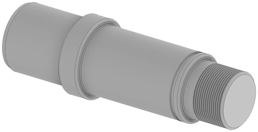 3D model · AL-033

You build the model. Draftneer prepares the drawing.
-
Step 1
Open the part or assembly
In Inventor, as every day. Nothing to export, nothing to upload.
-
Step 2
Press Generate drawing
Draftneer recognises what the part is (sheet metal, turned, milled, steel section, assembly, weldment) and prepares views, dimensions, sections and notes with your template.
-
Step 3
Check and sign
You get an .idw drawing to touch up as usual, the PDF and, for sheet metal, the DXF of the flat pattern. The summary points out what is worth checking.
Real capture in Inventor 2027: the part, the click, the drawing. The wait is shortened.
Every part with its own rules.
Real drawings, straight out of Draftneer with no touch-ups. Tap a sheet to enlarge it.
U bracketA3 · 1:1flat pattern + DXF
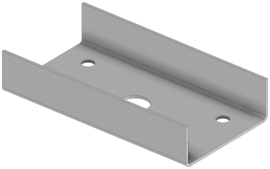
Sheet metal
Folded views, side profile and flat pattern, like a drawing made by hand.
- Dimensioned flat pattern with bend lines, bend notes and blank size, plus the DXF for laser cutting.
- Hole chains from edge to edge, in the views where the holes are seen face-on, with n× and thread notes.
- Flanges and bends dimensioned outside; bends other than 90° up to the virtual sharp, with their angle.
- Contours with inclined edges and fillets: vertices in chains, and radii.
Shaft AL-033A3 · 2:1sections B-B and A-A
Turned parts
Shafts, pins, bushes and flanges, dimensioned the way a turner reads them.
- Diameters from the smallest outwards, lengths referenced to the collar, tighter spacing when needed to fit the sheet.
- Threads read from the model («M25x1 - 6g») with their length; holes in the end face shown in section.
- Keyways and grooves: the keyway in section with the standard's tolerance, the retaining-ring groove with its diameter.
- Fits read from the assembly: «Ø30 k6» with its deviations and the matching roughness.
Milled plateA3 · 1:1two sections
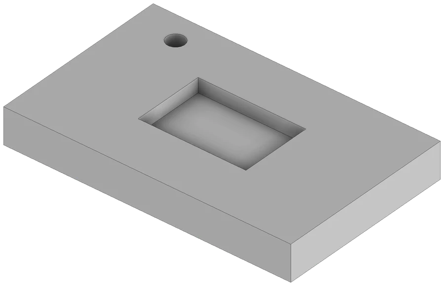
Milled parts
Plates, blocks and brackets, with sections where they are needed.
- Main view chosen from the part's shape, not from how it sits in the model.
- Sections where there are pockets, counterbores and blind holes: one horizontal and, if needed, one vertical.
- Holes with n×; tapped, countersunk and counterbored holes with the note read from the model; holes on a bolt circle with its Ø.
- One dimension per size: overall dimensions once, steps chained from edge to edge.
Complete rollerA3 · 1:2section + parts list
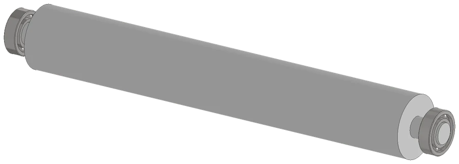
Assemblies
Parts list, balloons and position dimensions, without drawing the parts twice.
- Parts list above the title block, or on a sheet of its own when it is long, with quantities in pieces for steel sections too.
- Balloons in the section and the isometric view, with slanted leaders that are never mistaken for dimensions.
- Section along the axis for rollers and shafts with bearings, with screws and nuts left whole.
- Overall and position dimensions: where the body sits between the ends, shaft and body diameters.
Welded frameA3 · 1:5parts list with material
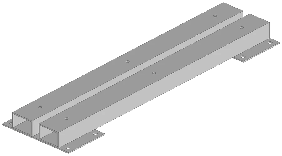
Weldments and steel sections
Light fabrication, from the cut section to the finished frame.
- Welded frame dimensioned as one part, with the parts list and each part's material.
- Sections UNP (UPN), IPE, HEA, HEB, hollow sections, angles and flats: the designation under the end view, length and holes.
- Mitre cuts with their angle, and broken views for long sections.
- Cut list as CSV for Excel, with the bars to order.
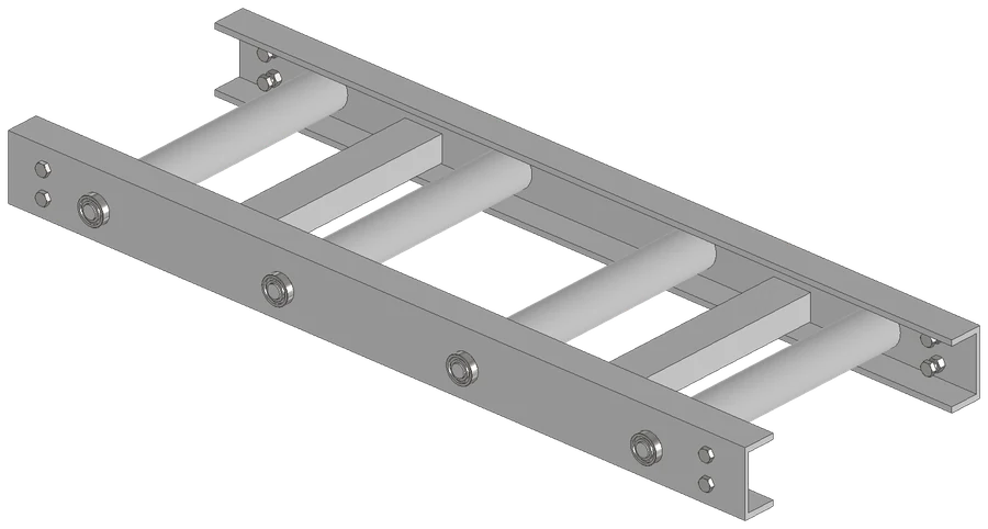 Part drawings
One click on the assembly, every part drawing.
“Part drawings” draws every part and sub-assembly to be made and saves drawing and PDF next to each file. One drawing per part even if the assembly uses it ten times: the summary says how many you need.
- Skips what is not drawn: purchased parts, Content Center fasteners, reference components.
- Leaves existing drawings alone, including the ones you corrected by hand.
- Adds tolerances and roughness where the assembly calls for them: the shaft in the bearing is k6, the housing H7.
- Prepares the cut list of steel sections, with lengths, end cuts, holes and bars to order.
| Code | Section | Length | End cuts | Holes | Qty |
|---|---|---|---|---|---|
| 61-longherone | UNP 100 | 1200 mm | 90° · 90° | 8 | 2 |
| 62-traverso | Tube 60×40×3 | 408 mm | 90° · 90° | 0 | 2 |
| To order: one 6 m bar of UNP 100 and one of 60×40×3 tube, with a 3 mm saw kerf. | |||||
Drawings come out the way your design office signs them.
A company profile holds the house rules. We set it up together once, then it applies to every drawing.
Border and title block for each format, filled in from the model's iProperties.
The smallest sheet where everything reads; a long parts list goes on a sheet of its own.
Standard scales only (1:1, 1:2, 1:5, 1:10…), with a minimum for assemblies.
In the title block; fit tolerances (k6, H7, f7) are taken from the assembly.
Ra 0.8 or 1.6 where the fit needs it, with the symbol outside the material.
View placement and section arrows follow the chosen method.
Your models stay yours.
Draftneer is an add-in: it works inside Inventor, on the designer's PC. No cloud upload, no model leaving the office.
- Drawings are saved in a folder next to the parts.
- The model is never sent outside your PC.
A designer's rules, written as code.
Draftneer is built together with mechanical designers: every rule comes from real drawings, the ones that go to the workshop.
Every version is tested on more than 50 parts, from sheet metal to welded frames, with nearly 600 automatic checks on dimensions, holes, bends and overlaps.
What it does not do, for now.
It does not sign for you
It prepares the drawing; checking and signing stay with the designer. The summary tells you what to review.
It does not invent design tolerances
It adds the ones that model and assembly allow it to derive; the others are added by hand, as today.
Inventor 2027, Italian interface
That is the version it runs on today, on Windows, with buttons and messages in Italian. If you use an earlier version, tell us: we are testing it.
Very unusual shapes
Hems, rolled sections, complex inner contours: it dimensions them in part and says so in the summary.
Frequently asked questions
Do I have to change how I model?
No. Draftneer reads models as they are: it recognises the part type from its shape, holes and threads from the features, material and title block data from the iProperties.
Can I edit the drawings?
Yes, they are standard Inventor drawings (.idw). Move, add or remove dimensions as you always have, then export the PDF again.
Can I use my own title block?
Yes. In the company profile you set your template for each format: border, title block and dimension styles come from there.
What happens to my files?
Nothing leaves your PC. Drawings are saved in a folder next to the parts, and existing drawings are never overwritten.
Which Inventor versions does it support?
Autodesk Inventor 2027 on Windows today. Earlier versions are being tested.
How much does it cost?
We are in the pilot phase with a few design offices and are setting the price together with them. Request a trial and let's talk.
Try it on your own parts.
We are looking for a few design offices for the pilot phase: you install Draftneer, use it on your models and tell us what you would change. We adapt it to your rules.
- Installation and company profile set up together.
- Direct contact with the people who build it.
- No commitment: if it doesn't help, uninstall it.
Prefer email? info@draftneer.com